Hand Laid Turnout Tutorial
Page 9
Now that the 2nd major part of the turnout is done, we'll finish it up by soldering the closure rail points to a pc board throwbar, attaching feeders and getting the switch machine in.
Now that most of the turnout is done, we'll jump to the easier task of installing the throwbar.
I use pc board ties from Fast Tracks for my thowbars. (refer to page 4 for info on these)
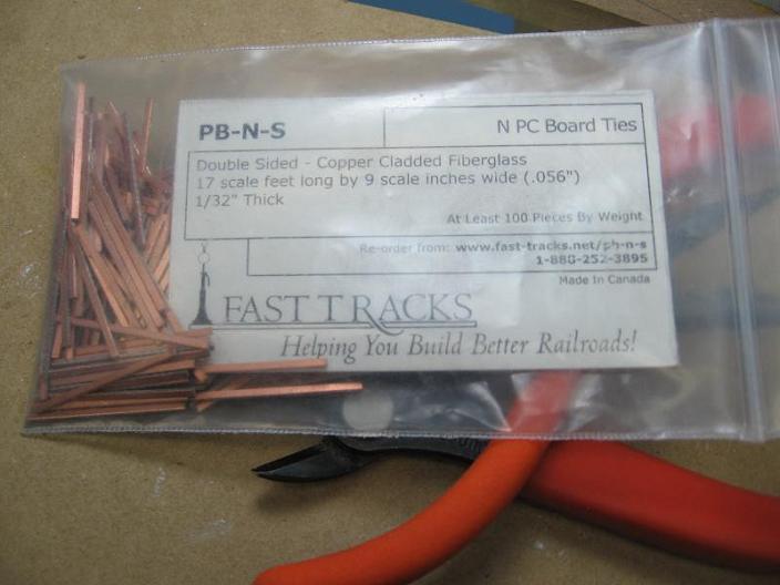
They are not as thick as a regular tie, which is good and bad (I'll explain this soon)
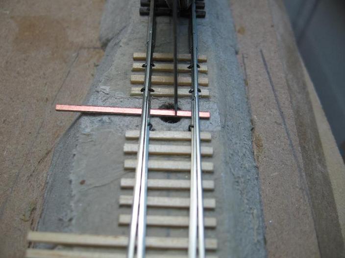
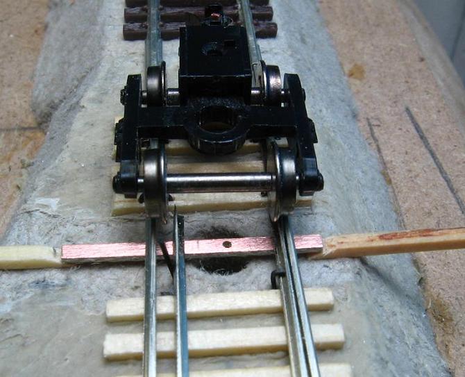
We'll take one of the pc board ties and slide it under the stock rails and points and center it in the throwbar area. I also take and align one side with the ends of the rest of the ties. This depends on which side you want to have your headblocks go to. In this case, it's aligned with the ties on the right of the picture, since the headblocks will go to the left of the pic.
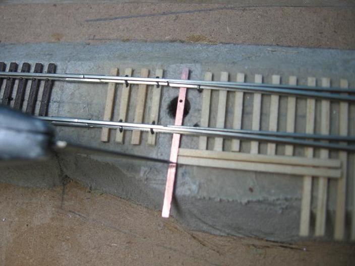
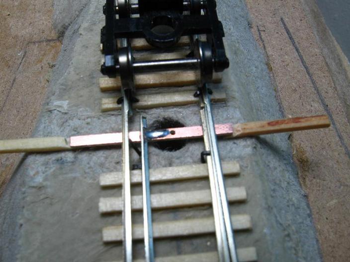
Depending on what kind of turnout control you are using, where you drill a hole at will be different. Since I'm using Tortoise switch machines, I'll need to mark on the throwbar where to drill a hole for the actuating wire. With the throwbar still lined up with the ties on the one side, I mark on the throwbar just past centerline towards the side that is even with the tie ends. This is because when the throwbar is moved towards this side, it will line up with, but not go past, the rest of the ties.
Making a mark
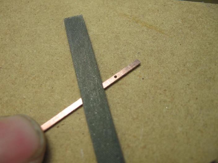
Now we can take the throwbar out and drill a hole in it. The spring steel wire that comes with the tortoises is .032" (I think ?) so this is the size I drill. Center the hole in the pc board throwbar.
Once the hole is drilled, I take the file and smooth out the throwbar. This roughs up the foil a bit so the solder will "grab" it better. It also takes off any small burrs that could get hung up on the turnout. Do all 4 sides and the ends. It doesn't take much. We don't want to file off the foil, just smooth it out.
With the pc board throwbar's hold drilled and smoothed out, we can put it back in and mark where to cut it. We don't need the whole thing sticking out and moving back and fourth, so we'll cut it shorter. I have found that I like it sticking out about 2 ties past the edge of the turnout. I take and line up the far side with the rest of the ties on that side and butt 2 ties up against the near side and make a mark for cutting.
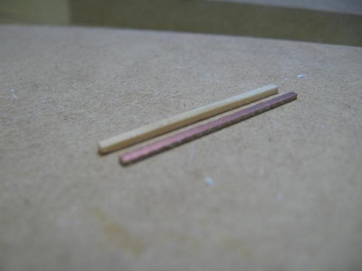
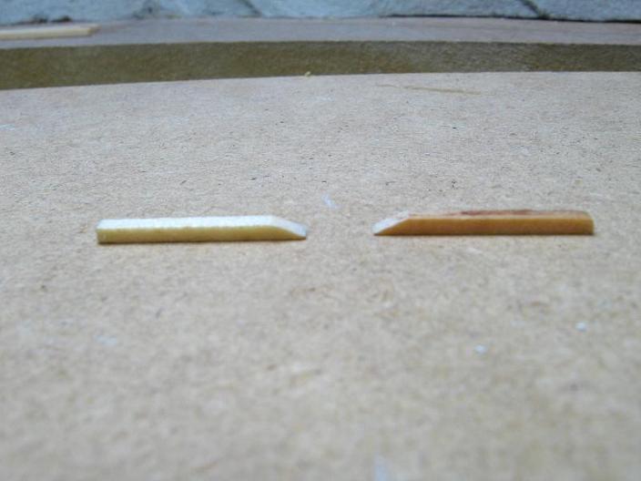
Now, back to that good and bad statement about the pc board. Because it is not as thick as a regular tie is good. That means it won't be making contact with the roadbed and possibly hanging up on any bumps/objects or causing resistance for the switch machine (although this area still should be as smooth as possible just in case). The bad thing is that if we slide the pc board under the stock rails and points, it sits too low and won't make contact with them for soldering. Here is the solution: take 2 scrap ties and file the ends at about a 35 degree angle, kinda like this:
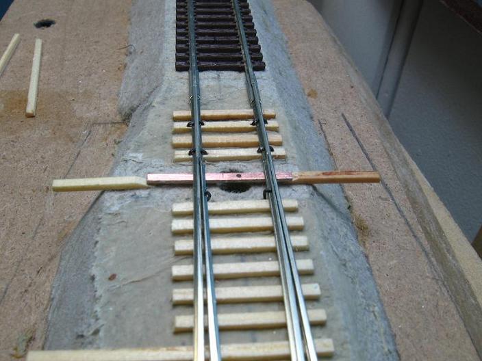
Now we can wedge these under the pc board, bringing it up nice and tight against our rails.
While these are wedged in, I like to take the file and rough up the web area of the point rails to give the solder a better chance to "grab" the rail.
After roughing up the rail some, take and center the pc board again in the throwbar area and line up the one end with the rest of the ties. Also make sure the wedges are in nice a good, since we don't want the pc board moving on us when we go to solder, which is coming up next.
With the pc board centered and lined up with the ties, we can take out the spike on the closure rail opposite the side of the lined up throwbar/ties. We'll take and move this rail in enough to clear the wheels so they don't touch it when rolling next to it. This is very important. If the wheel can touch, it will cause a short, so make sure it's not going to touch. Take and put in another temp spike to hold this rail in place.
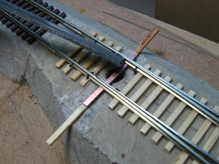
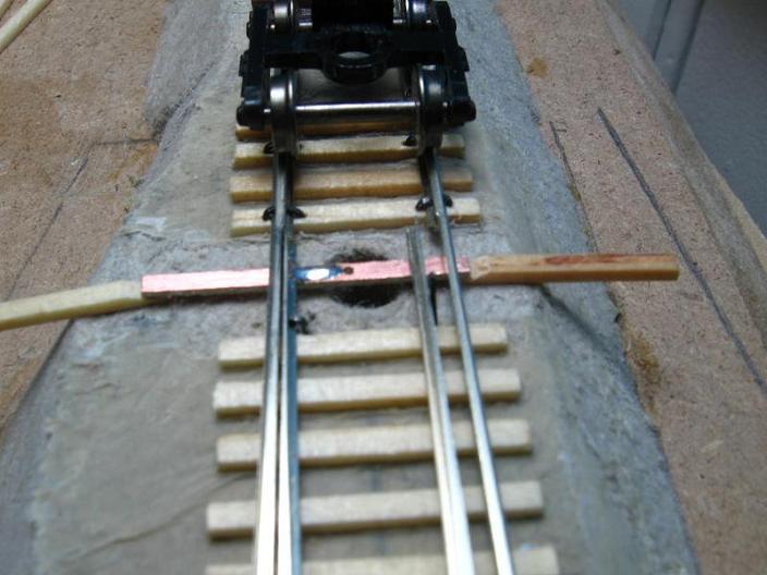
With everything lined up, we'll take and solder the rail to the pc board.
I take and put a dab of solder on the pc board right next to the rail, but far enough that I still see some pc board foil between it and the rail. I then put a small dab of solder on the web of the rail. Once both areas have solder, I then pull the small dab of solder on the pc board over to the rail until the whole area is connected. We don't want to spend alot of time in there with the iron, just enough to get solder on the 2 areas.
I do it this way for one big reason. If you put down too much solder too close to the rail, then it will run under the rail and come out on the back side of the rail. Then the rail won't close up nice and snug with the stock rail. If this happens, then it's time for a new throwbar and sometimes a whole new closure rail. Then you'll have to unspike it and replace it, and it's just best to avoid this hassle all together.
With the one side soldered, now we can jump to the other side. Pull the temp spikes out and slide the soldered rail over into position against the stock rail. Now we'll slide the other closure rail into postion, again checking that the wheels don't make contact with the rail, and then we can put in a temp spike to hold it in place for soldering.
Do the same thing as before for this side.
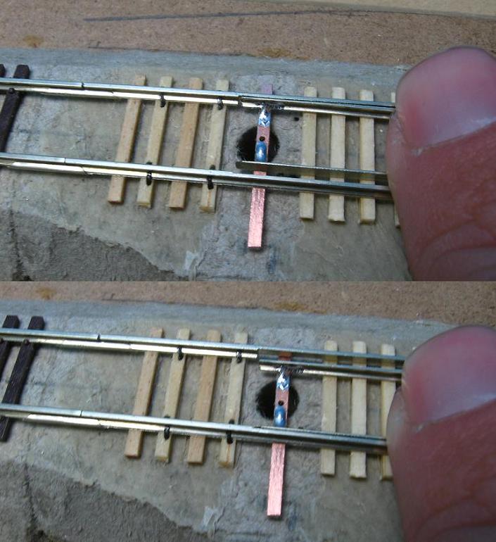
Once you have it soldered, take out the temp spike and the wedges and there you go, the throwbar is now soldered in!
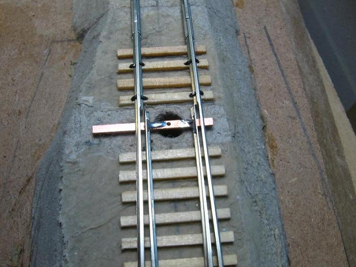
Now that the throwbar is soldered in, take your finger and slide the closure rails back and fourth. This whole thing should slide very smoothly with no hang ups at all. The points should go all the way over to each recessed area smoothly. If you have any tight areas, then check the throwbar for any burrs or check the rails as they could hang up on the ties somewhere.
All material on The Owens Valley Subdivision website is Copyright 2007-2009 by Michael Stoner. None of the material (including text and photographs) on this web site may be reproduced in any form without prior written permission.